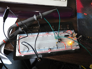
Red = ntsc signal
(they are scaled differently for easy viewing!)
the above image shows a complete NTSC field, plus the beginning of the next field.
The above image shows the beginning of an NTSC field. The left is the vsync pulse, the middle is the hidden VBI lines, and the right is the beginning of the visible lines (which are all black).


No comments:
Post a Comment